Welcome to Ask Us Whatever, I’m Joe Sorge.
In today’s episode, I’m going to describe an experiment that we did right here in our studio, to pursue our unexpected finding that the path of a focused light signal is influenced by the velocity of its source, regardless of the angle of source motion. I’m then going to build on this finding to present some new concepts regarding the momentum of light, the drag effect of a refractive medium, Snell’s law, the aberration of light, and I’ll then hint at the possibility that photons might have mass.
Although some of these new concepts seem to contradict the second postulate of Einstein’s 1905 Special Relativity paper, let’s look closely at what he actually wrote:
“Any ray of light moves in the “stationary” system of coordinates with the determined velocity c, whether the ray be emitted by a stationary or by a moving body.”
Einstein would say, for example, that a light beam emanating from the front of a rapidly moving train would travel no faster over the ground than a light beam emanating from a stationary train. I am now going to present evidence that this may not be true.
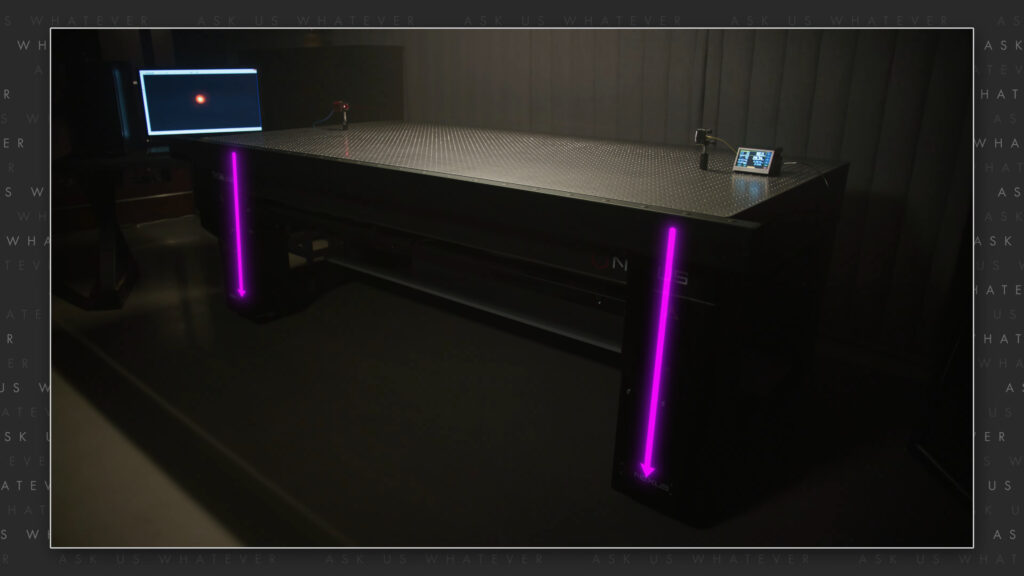
So, to start off, I’ll describe an experiment that we performed here in our studio.
It’s actually a partial repetition of an experiment published in 2002 by Kwik and Sikorski in the journal Europhysics Letters.
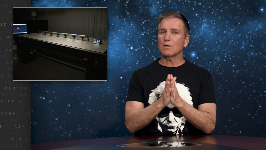
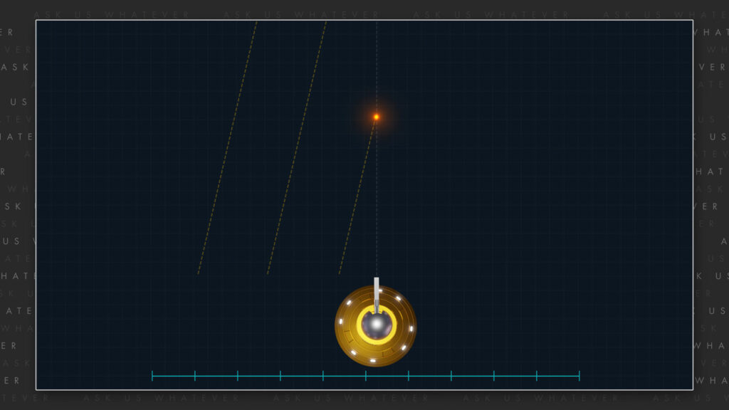
We took a columnated laser beam and aimed it at a CMOS detector chip.
I’ll spare you the details, but the pixels on the chip were several microns apart. If the light beam had no momentum, the speed of Earth’s orbit around the sun should have caused the beam to strike different pixels on the CMOS chip during different times of the day and night as the Earth’s rotation changed the orientation of our light table with respect to Earth’s yearly orbit around the sun.
And so, in the morning, our light table might have been moving about 30 thousand meters per second to the east relative to the Sun, whereas at night the same table would have been moving about 30 thousand meters per second to the west relative to the sun.
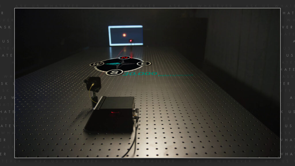
If the speed of the laser source through space had no impact on the lateral movement of light through space, the position of the light beam striking the CMOS chip should have shifted slightly to the west in the morning and slightly to the east in the evening.
Similar to the results of Kwik and Sikorski, we saw no change in the distribution of CMOS pixels that were excited by the laser signal during all 24 hours. There was no widening, narrowing, nor shift in the distribution of excited pixels. We also rotated our light table and saw no change in illuminated pixel distribution regardless of the table’s orientation.
One possible explanation is that air molecules absorb and re-emit the light energy and drag the light along with the air in the direction of Earth’s motion. This might actually be a contributing factor, but I don’t think it’s the whole story.
Because in 1925 Michelson and Gale did an experiment in which they passed light through a vacuum and saw no deviation in the path of the light signals during the day or night. Here air molecules could not have dragged the light, yet the light beam remained perfectly aligned with its target during all times of the day or night.
So even if air molecules play some role in the experiment we carried out here in our studio, something more fundamental seems to be at work.
In Episode 9.3, I argued against the partial ether drag model proposed by Hippolyte Fizeau in 1859, and introduced a model in which the molecules of a refractive medium fully drag light when light is absorbed by the molecules. Fizeau’s experiment used moving water to drag light parallel and antiparallel to the direction of the light signal. But what if a refractive medium moves at odd angles to the direction of the light signal? Will the signal be partially dragged or fully dragged?
To test this, we placed a glass tube between the laser and the CMOS chip.
When the setup is oriented such that, the Earth is moving at an angle with respect to the length of the tube, Fizeau might have expected the glass to have only partially dragged the light beam, in which case the light signal would have struck different pixels on the CMOS chip. But we saw no change in the distribution of excited pixels regardless of the time of day. Therefore, something was imparting Earth’s velocity to the light while it traveled from source to receiver.
Lastly, Before getting into details of our model, I’d like to comment on another possibility: gravity.
Can Earth’s gravitational field somehow drag the light signal in the direction of Earth’s motion? I don’t like this explanation for a couple of reasons. One is that Earth’s gravitational field is orthogonal to the direction of the light signal.
In other words, gravity would pull light “downward” toward the floor, not in the horizontal direction.
Another argument against gravity causing the light to remain in alignment with its target is that Michelson and Gale did observe a Sagnac effect due to the 24-hour rotation of the Earth. Gravity did not add or subtract the speed of the Earth to the co-rotating and counter-rotating light signals.
If it had, no Sagnac effect would have been observed. Instead, the Sagnac effect observed by Michelson and Gale was consistent with gravity having no impact on longitudinal light speed.
And for those of you who don’t trust 100-year-old experiments done outdoors, well Babcock and Bergman reported an experiment in 1964 in which they passed light over a six point closed loop path within a vacuum chamber in their laboratory and saw no deviation of the light path, regardless of the time of day.
And so, the explanation that I like best is momentum.
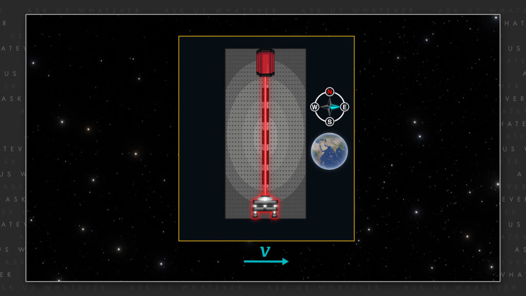
If the Earth, the laser, the light table, and the CMOS chip are all moving together,
and the light signal being emitted from the laser is given a component velocity equal to the speed of the laser source then light will travel toward the CMOS chip while also traveling with the lateral velocity of the laser, keeping it in perfect alignment with the chip.
As covered in Episode 9.3, if light is absorbed by intervening refractive molecules co-moving with the laser source and CMOS chip, then such absorbed light will continue to move with the component velocity of the molecules until re-emitted; and upon re-emission, the emitting molecules will also impart the same component velocity to the light.
Each emission event would be like shooting a bullet 90 degrees from the direction of a spaceship. The bullet will not only travel away from the spaceship due to the force of the round, but it will also drift at right angles together with the spaceship due to its momentum.
The concept of light momentum is really not foreign to physics. The momentum of light is generally written as, Planck’s constant times light’s frequency divided by light speed c.
\(p = \frac{hν}{c} \)
In Episode 9.3, I showed how we could deconstruct Einstein’s velocity addition formula into a ballistic speed and a refractive speed. We used Fizeau’s experiment with light traveling through moving water to work out a formula showing that the ballistic speed is the speed of the light source, and the refractive speed is a function of both the chemical nature of the refractive medium and the speed at which the refractive medium is moving with respect to the light signal.
\(u=\frac{dx}{dt} \)
\(u = u_r + u_b = \frac{\frac{c}{\gamma_L^2}}{n±wc}±w \)
\(u_r = \frac{\frac{c}{\gamma_L^2}}{n±\frac{w}{c}} \)
\(u_b=±w \)
But in the case of our experiment with the laser and the glass rod, the laser and the glass rod are moving with the Earth through space; and the velocity of the Earth through space does not always line up with the direction of the light signal.
Something caused the light signal to remain aligned with the target, even when the target was moving at off-angles with respect to the initial orientation of the light signal. I’m going to propose that this comes from the ballistic component of light speed.
So, it would be nice to have a formula where the ballistic and refractive velocities potentially move in different directions, yet will sum to the overall velocity of the light signal. So, let’s develop these formulas using the principles of my alternative model, because as we’ve shown in many other episodes, Special Relativity will eventually lead to problems.
Let’s start out with Snell’s Law, which was actually discovered by a Persian scientist Ibn Sahl in year 984. It states that the ratio of the sines of the angle of incidence and angle of refraction is equal to the inverse of the ratio of the refractive indices.
\(\frac{sin\theta_1′}{sin\theta_2′} = \frac{n_2}{n_1} = \frac{c/n_1}{c/n_2} \)
\(\frac{n_1}{n_2}sin\theta_1′ = sin_2′ \)
\(arcsin(\frac{n_1}{n_2}sin\theta_1′) = \theta_2′ \)
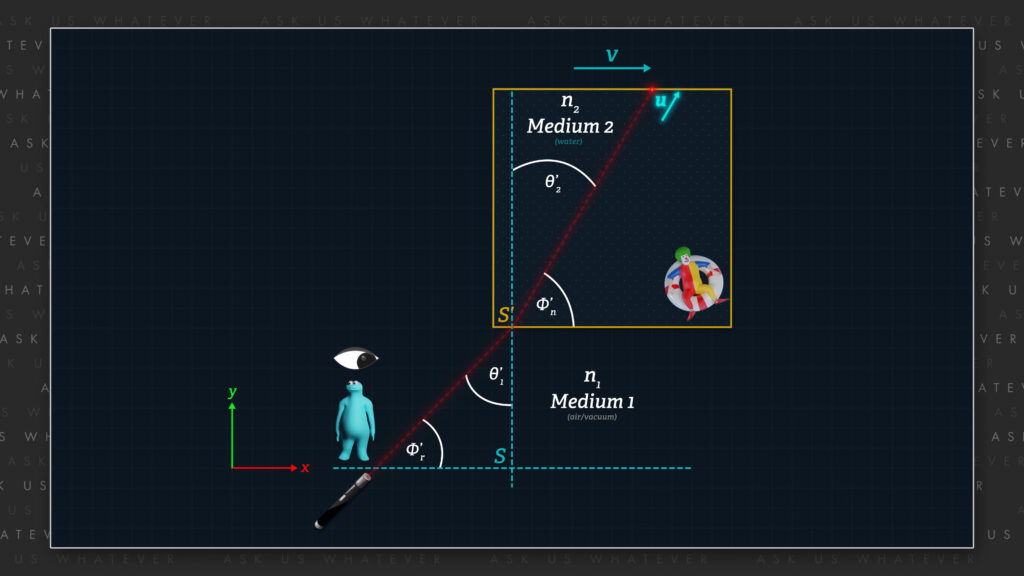
For example, if light approaches a refractive medium at angle theta prime 1 with respect to the line normal to the surface of the interface between the media (the y-axis in our diagram), it will be refracted to angle theta prime 2 as shown. And the sines of these two angles will be in proportion to the ratio of the speeds of light through the media, and inversely proportional to the refractive indices of the two media.
The angle at which light will pass through the second refractive medium will then be equal to the inverse sine of the ratio of n1 divided by n2 times the sine of the incident angle.
\(\theta_2′ = \) arcsin \(arcsin (\frac{n_1}{n_2}sin\theta_1′) \)
For example, if light strikes water at a right angle to the surface of the water, theta prime 1 will be zero, the sine of theta prime 1 will be zero, and theta prime 2 will also be zero. In other words, the light ray will not bend.
\(\theta_1′ = 0° \) \(sin\theta_1′ = 0 \) \(\theta_2′ = 0° \)
Whereas if theta prime 1 is 45 degrees to the line normal to the surface of the water, theta prime 2 will be less than 45 degrees if n2 is greater than n1.
\(\theta_1′ = 45° \) if \(n_2 > n_1\), then \(\theta_2′ < 45°\)
Now let’s make it more challenging. What if the refractive medium moves in the x-direction with respect to our stationary frame?
Let’s say that the refractive medium represents moving Frame S’ and we’ll place observers in both Frames S’ and S.
When light strikes the interface between refractive medium 1, which we will say is in Frame S, and refractive medium 2, which we will now say is in Frame S’, Snell’s Law will cause the direction of the light signal to change as described. And once that occurs, we can focus on the new angle – n’ (phi-prime-sub n) – as the angle light will travel through Frame S’.
If refractive medium-2 moves in the x-direction at velocity v with respect to the stationary Frame S, the refractive medium absorbs and then re-emits the light, causing the medium to impart a ballistic velocity v to the light.
As we learned in Episode 9.3, the speed of light passing through a refractive medium with refractive index n that is stationary relative to the Earth is equal to c’ divided by n meters per second’.
light speed in earth frame \(S’ = \frac{dr’}{dt’} = \frac{c}{n} meters/second’ \)
When I refer to the refractive index as n instead of n-sub-2, refractive medium 1 is either vacuum or air, in which case n-sub-1 is simply equal to 1 and therefore we drop the subscripts.
Note that the value of n is a measured value. That is, it is obtained typically by making round-trip measurements on the Earth. These measurements can be thought of as Earth-Frame-S’ empirical measurements because the Earth is moving through space.
The goal now is to solve for the velocity of light traveling through the refractive medium as observed from a stationary Frame S. We typically refer to this as a scaler speed u, but since we are now looking at different angles, we will refer to it as a vector speed, u (bold u).
If we believe in Fresnel’s and Fizeau’s partial ether drag hypothesis, then the movement of the refractive medium will contribute only a partial component of velocity v to velocity u. But according to my ballistic model, and as explained in Episode 9.3,
not only do the molecules of refractive medium carry the light signal while light energy is absorbed within the molecules, but those molecules also impart the full value of velocity v when they emit the light signal.
Our formula for u from Episode 9.3 was, c divided by gamma-s all divided by n-sub-2 plus or minus w over gamma-s times c, all plus or minus w, where w was the speed of the water.
\(u = \frac{dx}{dt} = \frac{\frac{c}{\gamma_s}}{n_2±\frac{w}{\gamma_sc}}±w\) meters/second
The subtleties of this formula are explained in Episode 9.3, but please note that since the light signal and the water speed were both in the x-direction, there was no y-component to speed u, nor was there a cosine or sine term.
In Episode 9.3 I focused on water speeds, that’s why I used the symbol w to represent the speed of the refractive medium. Now I will generalize the concept to any refractive medium (or emitter) and henceforth will use the symbol v to symbolize the x-directional speed of the refractive medium or emitter.
\(u = \frac{dx}{dt} = \frac{\frac{c}{\gamma_s}}{n_2 ± \frac{v}{\gamma_sc}} v\) meters/second
If we adapt the formula to the present setup where light is traveling through the refractive medium at the complement of the Snell angle, phi-prime-sub-n, relative to the x-axis, we obtain these new formulas.
\(u = \sqrt{{(\frac{dx}{dt})}^2 + {(\frac{dy}{dt})}^2}\)
\(\frac{dx}{dt} = \frac{\frac{c}{\gamma_s}}{n_2 ± \frac{v}{\gamma_sc}cos\phi_n’}cos\phi_n’±v \)
\(\frac{dy}{dt} = \frac{\frac{c}{\gamma_s}}{n_2 ± \frac{v}{\gamma_sc}cos\phi_n’} sin\phi_n’ \)
*n2 is for refractive media
OK, let’s pause.
How many of you think I’m just pulling ideas out of the ether? I hope there’s a few of you, because I now want to want to surprise you. Let’s take a relativistic approach to the problem and use the relativistic velocity addition formula to add velocity components.
We can express the velocity of light moving at the complement of the Snell angle as x’ and y’ speeds relative to Frame S’.
The speed relative to the x’-axis will be, c divided by n times the cosine of angle phi-prime-sub-n. And the speed relative to the y’-axis will be c divided by n times the sine of angle phi-prime-sub-n.
\(u_{x’} = \frac{dx’}{dt’} = \frac{c}{n} cos\phi_n’ \) meters/second’
\(u_{y’} = \frac{dy’}{dt’} = \frac{c}{n} sin\phi_n’ \) meters/second’
Now the relativistic velocity addition formula of the alternative model is, gamma-s times dx’/dt’ plus v all divided by 1 plus v times dx’/dt’ over gamma-s times c-squared. This is the same as Einstein’s relativistic velocity addition formula after dispensing with the absurd notion of length contraction.
\(u_x = \frac{\gamma_s \frac{dx’}{dt’} + v}{1 + \frac{v\frac{dx’}{dt’}}{\gamma_sc^2}} \)
Let’s substitute the x’ component-speed for dx’/dt’ into the relativistic velocity addition formula,
\(u_x = \frac{\gamma_s \frac{c}{n} cos\phi_n’+v}{1 + \frac{v\frac{c}{n} cos\phi_n’}{\gamma_s c^2}} \)
and simply separate the numerator into its two terms.
\(u_x = \frac{\gamma_s \frac{c}{n} cos\phi_n’}{1 + \frac{v \frac{c}{n} cos\phi_n’}{\gamma_s c^2}} + \frac{v}{1 + \frac{v \frac{c}{n} cos\phi_n’}{\gamma_sc^2}} \)
Now, let’s carry out a little math trick by adding and subtracting a temporary term I’ll call Z.
\(u_x = \frac{\gamma_s \frac{c}{n} cos\phi_n’}{1 + \frac{v \frac{c}{n} cos\phi_n’}{\gamma_s c^2}} – Z + \frac{v}{1 + \frac{v \frac{c}{n} cos\phi_n’}{\gamma_s c^2}} + Z \)
Let’s solve for Z by forcing the right two terms equal to v.
\(u_x(\text{right term}) = v = \frac{v}{1 + \frac{v \frac{c}{n} cos\phi_n’}{\gamma_s c^2}} + Z \)
By rearranging we obtain Z.
\(Z = v – \frac{v}{1 + \frac{v \frac{c}{n} cos\phi_n’}{\gamma_s c^2}} \)
\(Z = \frac{\frac{v^2 \frac{c}{n} cos\phi_n’}{\gamma_s c^2}}{1 + \frac{v\frac{c}{n} cos\phi_n’}{\gamma_s c^2}} \)
OK then let’s subtract capital Z from the left term of the magical velocity addition formula.
\(u_x = \frac{\gamma_s \frac{c}{n} cos\phi_n’}{1 + \frac{v \frac{c}{n} cos\phi_n’}{\gamma_s c^2}} – Z + \frac{v}{1 + \frac{v \frac{c}{n} cos\phi_n’}{\gamma_s c^2}} + Z\)
\(Z = \frac{\frac{v^2 \frac{c}{n} cos\phi_n’}{\gamma_s c^2}}{1 + \frac{v \frac{c}{n} cos\phi_n’}{\gamma_s c^2}} \)
\(u_x (\text{left term}) = \frac{\gamma_s \frac{c}{n} cos\phi_n’}{1 + \frac{v\frac{c}{n} cos\phi_n’}{\gamma_s c^2}} – Z \)
\(u_x (\text{left term}) = \frac{\gamma_s \frac{c}{n} cos\phi_n’}{1 + \frac{v \frac{c}{n} cos\phi_n’}{\gamma_s c^2}} – \frac{\frac{v^2 \frac{c}{n} cos\phi_n’}{\gamma_s c^2}}{1 + \frac{v \frac{c}{n} cos\phi_n’}{\gamma_s c^2}} \)
And we will now multiply numerator and denominator by gamma-s times n and combine terms.
\(u_x (\text{left term}) = \frac{\gamma_s^2 c cos\phi_n’ – c cos\phi_n’ \frac{v^2}{c^2}}{\gamma_s n + \frac{v c cos\phi_n’}{c^2}} \)
\(\gamma_s^2 = 1 + \frac{v^2}{c^2} \)
And since gamma-s squared is 1 plus v-squared over c squared, the left term of the magical velocity addition formula becomes, the refractive term of our linear velocity addition formula. Well, look at that!
\(u_x (\text{left term}) = \frac{\frac{c}{s} cos\phi_n’}{n + \frac{v}{\gamma_s c} cos\phi_n’} \)
And since the right term of the magical velocity addition formula is now v,
\(u_x (\text{right term}) = v = \frac{v}{1 + \frac{v \frac{c}{n} cos\phi_n’}{\gamma_s c^2}} + Z \)
we get the x-component of velocity in Frame S.
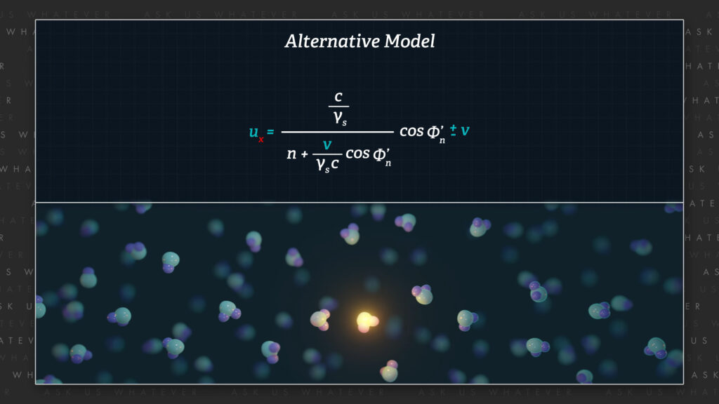
\(u_x = u_x (\text{left term}) + u_x (\text{right term}) = \frac{\frac{c}{\gamma_s}}{n + \frac{v}{\gamma_s c}cos\phi_n’} cos\phi_n’ ± v \)
The x-component of u equals our formula for the simple linear addition of velocity pointed in the direction of source motion plus a term that perfectly fits a model in which light is either volleyed from molecule to molecule, like a silver ball in a pinball machine, or merely works its way from source to receiver through a field created by the refractive medium moving at speed v.
If we follow the same logic for the y-component of light speed, we find that
\(u_{y’} = \frac{dy’}{dt’} = \frac{c}{n_2} sin\phi_n’ \)
when the value c divided by n times the sine of phi-prime-sub-n is plugged into the relativistic velocity addition formula for motion in the y-direction, we obtain the formula that I showed earlier for the y component of light speed in frame S.
\(u_y = \frac{dy}{dt} = \frac{\frac{c}{\gamma_s}}{n_2 ± \frac{v}{\gamma_s c} cos\phi_n’} sin\phi_n’ \)
Therefore, we can describe the speed and direction of light traveling through a moving, refractive medium at any angle with our formulas for x and y speed.
\(u_x = \frac{dx}{dt} = \frac{\frac{c}{\gamma_s}}{n_2 ± \frac{v}{\gamma_s c} cos\phi_n’} cos\phi_n’ ± v \)
\(u_y = \frac{dy}{dt} = \frac{\frac{c}{\gamma_s}}{n_2 ± \frac{v}{\gamma_s c} cos\phi_n’} sin\phi_n’ \)
These formulas are very similar except that the x-component is modified by the cosine of phi-prime-sub-n, and the y-component is modified by the sine of phi-prime-sub-n; and in addition, because the speed of frame S’ is constrained to the x-axis, the formula for the x-component also includes the speed of frame S’, shown as plus or minus v. That is, we are adding the speed of frame S’, which is the speed of the emitter, to the x-component of light traveling through the refractive medium.
I’m sorry but I have to belabor this, because it’s so important. The ratios of these formulas,
\(u_x = \frac{dx}{dt} = \frac{\frac{c}{\gamma_s}}{n_2 + \frac{v}{\gamma_s c}cos\phi_n’}cos\phi_n’ ± v \)
\(u_y = \frac{dy}{dt} = \frac{\frac{c}{\gamma_s}}{n_2 ± \frac{v}{\gamma_s c} cos\phi_n’} sin\phi_n’ \)
represent the speed of light through the refractive medium, frame S’, as measured from frame S. We then simply add the speed of frame S’, which is v, to the x-component of velocity to obtain the total x-component of light speed through frame S. There’s no magical velocity addition. The x-component of light speed is simply the linear addition of light’s speed through the refractive medium, shown in the ratio, plus the speed of the refractive medium.
So why is this so important? Well, let’s see what happens when light travels solely in the x-direction.
The speed of light traveling longitudinally through the vacuum of space relative to Frame S’, in other words when the cosine of phi-prime-sub-n equals 1, and a refractive index of space is equal to 1, will be c divided by gamma(s) meters per stationary Frame second, divided by 1 plus or minus the speed of Frame S’ divided by gamma(s) times c plus or minus the speed of Frame S’.
\(cos\phi_n’ = 1 \) \(n_2 = n_\text{space} = 1 \)
\(\frac{dx}{dt} = \frac{\frac{c}{\gamma_s}}{n_2 ± \frac{v}{\gamma_s c}} ± v \)
Then dx/dt becomes equal to gamma(s) times c.
\(\frac{dx}{dt} = \frac{\frac{c}{\gamma_s}}{1 ± \frac{v}{\gamma_s c}} ± v = \frac{\frac{c}{\gamma_s} ± v ± \frac{1}{\gamma_s} \frac{v^2}{c}}{1 ± \frac{v}{\gamma_s c}} = c \frac{1±\gamma_s \frac{v}{c} ± \frac{v^2}{c^2}}{\gamma_s ± \frac{v}{c}} = \)
\(= \frac{c(\gamma_s^2 ± \gamma_s \frac{v}{c})}{(\gamma_s ± \frac{v}{c})} = \frac{\gamma_s c (\gamma_s ± \frac{v}{c})}{(\gamma_s ± \frac{v}{c})} = \gamma_s c \)
Isn’t that amazing?! Einstein doesn’t have an explanation for why light travels at speed c in all directions in Special Relativity – he just assumes it in a postulate! But I have an explanation for why light travels at speed gamma(s) times c in the alternative model.
It’s the linear addition of the speed of light relative to the moving Frame S’
\(u_x = \frac{\frac{c}{\gamma_s}}{n ± \frac{v}{\gamma_s c}} ± v \)
plus the speed of Frame S’,
\(u_x = \frac{\frac{c}{\gamma_s}}{n ± \frac{v}{\gamma_s c}} ± v \)
both measured with Frame S clocks!
And if the source and receiver happen to be stationary in Frame S then light travels at speed c through the vacuum of space. This is because v is equal to zero and gamma-s is equal to one when the source is not moving. In other words, light emitted by a source that is stationary in frame S will travel at speed c, whereas light emitted from a source that is moving through frame S will travel at speed gamma-s times c.
\(u_x = \frac{\frac{c}{\gamma_s}}{n_2 ± \frac{0}{\gamma_s c}} ± 0 \) \(v = 0 \)
\(u_x = \frac{\frac{c}{1}}{n_2 ± 0} ± 0 \) \(v = 0 \) \(s = 1 \)
\(u_x = \frac{\frac{c}{1}}{1 ± 0} ± 0 \) \(v = 0 \) \(s = 1 \) \(n = 1 \)
\(u_x = \frac{c}{1 ± 0} ± 0 = c \) \(v = 0 \) \(s = 1 \) \(n = 1 \)
Finally, total speed u of light passing through Frame S is the square root of the sum of the squares of the x- and y- components of Frame S speed.
\(u = \sqrt{(\frac{dx}{dt})^2 + (\frac{dy}{dt})^2} \)
And we can solve for the direction of the light signal vector u in Frame S by taking the inverse tangent of the ratio of the y-component of light speed divided by the x-component of light speed.
\(\phi_s = \) arctan \(arctan (\frac{dy/dt}{dx/dt}) \)
This angle, which I call phi-sub-s, can also be obtained directly with the following formula, the sine of the complement of the Snell angle, divided by gamma-s-squared times the cosine of the complement of the Snell angle plus gamma-s times the refractive index of the moving medium times the ratio of Frame S’ speed divided by c.
\(\phi_s = \) arctan \(arctan ( \frac{sin\phi_n’}{\gamma_s^2 cos\phi_n’ + \gamma_s n_2 \frac{v}{c}}) \)
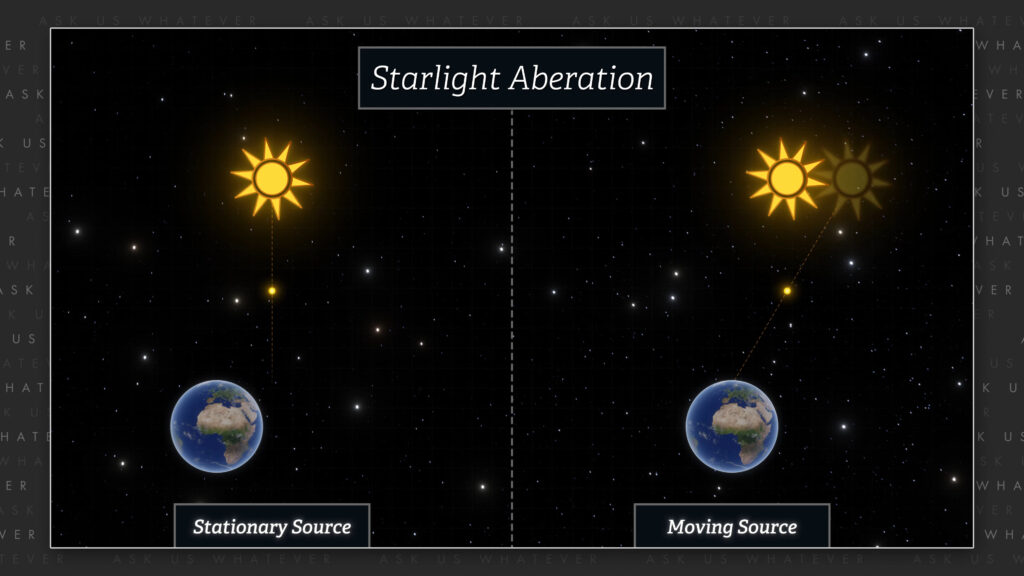
Believe it or not, this is an aberration angle. You may have heard about the aberration of starlight. It’s often explained with a stationary star and a moving Earth. We will get into that in another episode, but here we have a moving emitter (the molecules of the refractive medium) and a stationary observer in Frame S. The angle phi-sub-s is the stationary frame aberration angle when light is emitted by a moving source at the complement of the Snell angle in Frame S’.
If we wished to eliminate the refractive medium from the setup and just use a laser emitter moving at speed v in the x-direction, then n2 would be equal to 1 and the complement of the Snell angle would be replaced with the Frame S’ emission angle.
The frame S’ emission angle was 90° pointing directly at the CMOS chip, and so the cosine of phi prime sub n was zero. The sine of phi prime sub n was equal to 1. N2 was essentially equal to 1 in air, and our aberration angle was the inverse tangent of c divided by gamma s times V.
\(cos\phi_n’ = 0 \) \(sin\phi_n’=1 \) \(n_2 ≈ \)1
\(\phi_s =\) arctan \(arctan (\frac{c}{\gamma_s v}) \)
This is the angle at which an observer in space would see our laser beam move when traveling toward the CMOS chip. But to observers in Frame S’, the light travels directly from laser to CMOS chip without deviation.
This explains our laser/CMOS result at the molecular level. Special Relativity does not, because Special Relativity scales velocities v and u’ identically. Special Relativity does not explain the molecular behavior of light traveling through a refractive medium at an angle that is different from motion of the refractive medium through Frame S.
My ballistic model explains this perfectly. Isn’t that beautiful?
Apparently, light is more complicated than simply being a wave that finds the shortest path from source to receiver because it also carries the full speed of its source, like a bullet being fired from a gun in space. This explains Fizeau’s result on a molecular level and contradicts Einstein’s implication that source speed has no effect.
Now I’m going to speculate even more, since this is getting fun. Do you know one of the main reasons why physicists believe that light is massless? It’s because Special Relativity defines energy as the Lorentz gamma factor times the rest mass times c-squared.
\(Energy = \gamma_L m_0 c^2 \)
And since light is presumed to travel at speed c, the Lorentz gamma factor becomes infinitely large, which would be impossible if light had a rest mass. Light would have infinite energy, unless, of course, it had zero rest mass.
\(\gamma_L = \frac{1}{\sqrt{1-\frac{c^2}{c^2}}} = ∞ \)
So, physicists therefore reason that infinity times zero times c-squared equals – well, Planck’s constant (h) times light’s frequency (ν).
\(Energy = \gamma_L m_0 c^2 = ∞ 0 c^2 = hν \)
What? It’s like someone pulled this out of their navel!
Now I’m not saying that I have the real answer, because it’s obviously complicated. But I am saying that I have something for you to think about.
As you know, the alternative model has light traveling through Frame S at gamma-s times c, where gamma-s is the square root of one plus v-squared over c-squared, where v is the speed of the source relative to the universal, stationary frame (which we jokingly call the cosmic train station).
\(\text{Light speed in frame S (Alt)} = \gamma_s c \)
\(\gamma_s = \sqrt{1 + \frac{v^2}{c^2}} \) \(\gamma_L = \frac{1}{\sqrt{1 – \frac{v^2}{c^2}}} \)
And if a component of energy were to be equal to gamma-s times mc-squared (instead of the Lorentz gamma factor times mc-squared), then light coming from an emitter traveling at or close to speed c does not have a prohibitively infinite energy!
\(\text{Light’s Ballistic Energy (Alt)} = \gamma_s mc^2 = \sqrt{1+\frac{v^2}{c^2}} * mc^2 \)
\(\text{Light’s Ballistic Energy (Einstein)} = \gamma_L mc^2 = \frac{1}{\sqrt{1 – \frac{v^2}{c^2}}} * mc^2 \)
And if gamma-s at speed c is not infinite, then photons do not need to be massless. We can be perfectly content with them traveling at speed c while having a very tiny mass. And if they have a very tiny mass, then they could have a very tiny momentum.

Look, I’m not saying that photons have mass, nor do I have this all figured out (yet :D). I’m just saying that the standard reasoning for photons being massless is questionable. And that’s fun!
Well, if you lasted through this episode, you’ve learned that light’s velocity may be deconstructed into a ballistic velocity equal to the velocity of its source, plus a refractive velocity related to the nature of the medium it travels through. We’ve learned that the ballistic velocity and the refractive velocity need not point in the same direction, and that the sum of these two velocities form an aberration angle as observed from Frame S which is different than the Snell angle as observed from Frame S’.
And finally, we have opened the door to exploring the possibility that there is a mass-like component to light.
OK, if you have any questions, please write them in the comments section. I’m Joe Sorge, and thanks for watching!